


Introducing Spatial Mapping and Meshing
Our 0.11.1 SDK release introduced the Spatial Mapping and Meshing feature to the Snapdragon Spaces™ developer community. Read on to learn more about our engineering team approach, use cases and important factors to consider when getting started.
April 7, 2023
What is Spatial Mapping and Meshing?
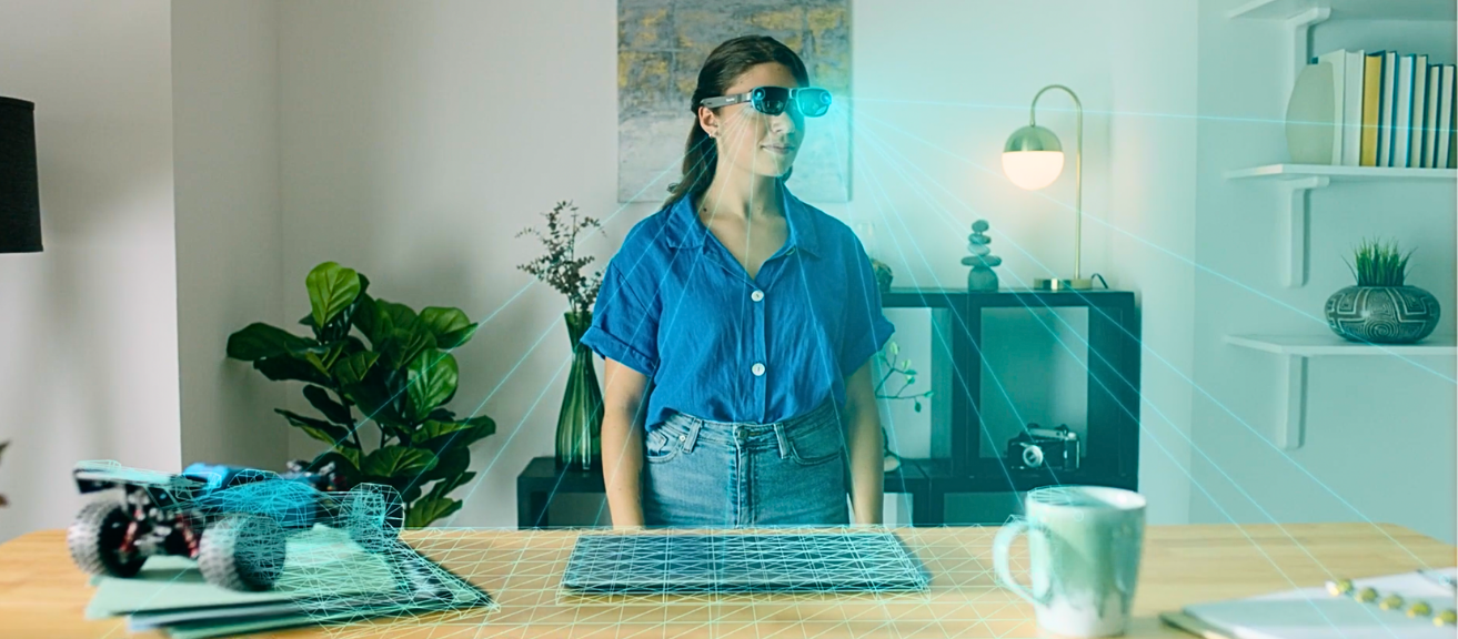
Spatial Mapping and Meshing is a feature of Snapdragon Spaces SDK that provides users with an approximate 3D environment model. This feature is critical in helping smart glasses understand and reconstruct the geometry of the environment.
Spatial Mapping and Meshing offers both a detailed 3D representation of the environment surrounding the user and a simplified 2D plane representation. Meshing is needed to calculate occlusion masks or running physics interactions between virtual objects with the real world. Snapdragon Spaces developers can access to every element of the mesh (vertex) and request updates to it. Planes are used whenever just a rough understanding of the environment is enough for the application.
For example, when deciding to place an object on top of a table, or a wall. Only the most important planes are returned by the API, since there is a trade-off between how many planes can be extracted and how fast they can be updated with new information from the environment.
In addition to meshes and planes, developers can use collision check to see whether a virtual ray intersects the real world. This is useful for warning the user when they approach a physical boundary – either for safety or for triggering an action from the app.
Why use Spatial Mapping in your AR experiences?
A big part of how well users perceive your app lies in understanding the environment and adapting your application to it. If you strive to achieve higher realism for your digital experiences, Spatial Mapping and Meshing is the right choice. Why? As humans, we can understand the depth of space using visual cues that are spread around us in the real world. Occlusion is one of the most apparent depth cues – it happens when parts or entire objects hide from view, covered by other objects. Light also provides plenty of other natural depth clues – like shadows and glare on objects. Spatial Mapping and Meshing allows to emulate human vision and provide vital information to your augmented reality app to intake depth cues from the real world.
“The Sphere team has been incredibly excited for the Snapdragon Space’s release with Spatial Mapping and Meshing” says Colin Yao, CTO at Sphere. “Sphere is an immersive collaboration solution that offers connected workforce use-cases, training optimization, remote expert assistance, and holographic build planning in one turnkey application. As you can imagine, spatial mesh is a fundamental component of the many ways we use location-based content. By allowing the XR system to understand and interpret the physical environment in which it operates, we can realistically anchor virtual objects and overlays in the real-world” adds Yao. “Lenovo’s ThinkReality A3 smart glasses are amongst the hardware we support, and Sphere’s users that operate on this device will especially benefit from Spatial Mapping and Meshing becoming available.”
How does Snapdragon Spaces engineering team approach Spatial Mapping and Meshing?
Our engineering team’s approach to Spatial Mapping and Meshing is based on two parallel components – frame depth perception and 3D depth fusion. Read on to learn more about each.


Frame Depth Perception We leverage the power of machine learning by training neural networks on a large and diverse set of training data. Additionally, our data set benefits from running efficiently on the powerful Snapdragon® neural processor chips. To scale the diversity and representability of our training datasets, we do not limit the training data to supervised samples (e.g. set of images with measured depth for every pixel). Instead, we leverage unlabelled samples and benefit from self-supervised training schemes. Our machine learning models are extensively optimized to be highly accurate and computationally efficient compared to sensor-based depth observations – all thanks to a hardware-aware model design and implementation.
3D Depth Integration The 3D reconstruction system provides a 3D structure of a scene with a volumetric representation. The volumetric representation divides the scene into a grid of cells (or cubes) of equal size. The cubes in the volumetric representation (we’ll call them samples in this article) stores the signed distance from the sample centre to the closest surface in the scene. This type of 3D structure representation is called the signed distance function (SDF). Free space is represented with positive values that increase with the distance from the nearest surface. Occupied space is represented as samples with a similar but negative value. The actual physical surfaces are represented in the zero-crossings of the sample distance.
The 3D reconstruction system generates the volumetric representation by fusing and integrating depth images into the volumetric reconstruction. For each depth image, the system also requires its pose (camera location and viewing orientation) at the acquisition timestamp, correlated with a global reference coordinate system. The 3D reconstruction system also extracts a 3D mesh representation of the surfaces in the volumetric reconstruction. This is done using a marching cubes algorithm that looks for the zero iso-surface of signed distance values in the grid samples. 3D reconstruction in its entirety is a rather complex and resource-intensive operation. Enabling the mesh of the environment in your XR app brings benefits and feature possibilities that often make it worth the computational cost.
Enabling realism with Spatial Mapping and Meshing
Virtual Object Occlusion Creating augmented reality experiences without occlusion has been common practice for a long time. Having an approximate mesh of the environment can be used to create virtual objects that are occluded by real objects. By leveraging the depth buffer by rendering the environment mesh into the buffer, together with all other virtual objects in your scene, you can effortlessly create occlusion effects. To achieve this effect, you need to create a transparent shader that still writes into the depth buffer.
Virtual lighting and shadows in the real world Similarly, the mesh of the real environment can be used to apply virtual lighting effects to the real world. When creating a virtual light source without a mesh of the environment, only virtual objects will be lit by this virtual light. This can cause some visual discrepancies. When there is a model of the real world that is lit, the discrepancy will be less visible. Shadows again behave quite similarly. Without a model of the environment, shadows coming from virtual objects will not throw a shadow on the real world. This can cause confusion about the objects’ depth and even give users the impression that objects are hovering. To achieve this effect, you need to create a transparent shader that receives lighting and shadows like an opaque shader.
Real lighting and shadows in the virtual world When combining virtual and real-world content it’s often very easy to spot where a virtual object starts and reality ends. If your goal is to have the most realistic augmentations possible you need to combine real and virtual lighting and shadows. You can do this by having light estimation emulate the real-world lighting conditions with a directional light in your scene. Combined with meshing, light estimation allows you to throw shadows from real world objects onto virtual objects.
Limitations Depending on your hardware, there will be certain limitations to the precision of the detected mesh. For example, Lenovo ThinkReality A3 uses a monocular inference-based approach, which can yield certain imprecisions. Transparent objects (such as glass or glossy surfaces) will lead to fragmentations or a hole in the mesh. The further away a real-world object is from the glasses, the less precise the generated mesh for it will be. Quite logical if you think of it – the RGB sensor loses information with distance. The mesh is available for a distance up to 5 meters from the user. Other methods of depth measurement (such as LIDAR) require specialized hardware. There is a cost-effect trade-off. While LIDAR could provide a higher precision for some use cases, RGB cameras are available in most devices already and are more affordable.
Next steps
Refer to Snapdragon Spaces documentation to learn more about Spatial Mapping and Meshing feature and use Unity sample and Unreal sample to leverage Spatial Mapping and Meshing feature.
Snapdragon branded products are products of Qualcomm Technologies, Inc. and/or its subsidiaries.